Now that we covered the basic building blocks of 3D modeling, let’s look at what we can do with them. At its core, 3D modeling is pretty straight forward and is built around a few core operations. Although the names may change from application to application, the following instruction should be applicable to any modern 3D modeler.
In order to understand this chapter, you are going to need to be familiar with the concept of axis ( x,y,z ) to describe directions. If you aren’t really comfortable with the concept I suggest you check out this post. Oh and for the record the plural of axis is actually axes, but that is exceedingly confusing to read, especially if the concept is new to you! So the earlier typo was intentional.
The three most common actions you will perform are translate, scale, and rotate. All three of these tasks can be performed on the entire object, or a component of it, such as a face or edge.
Translate / Move
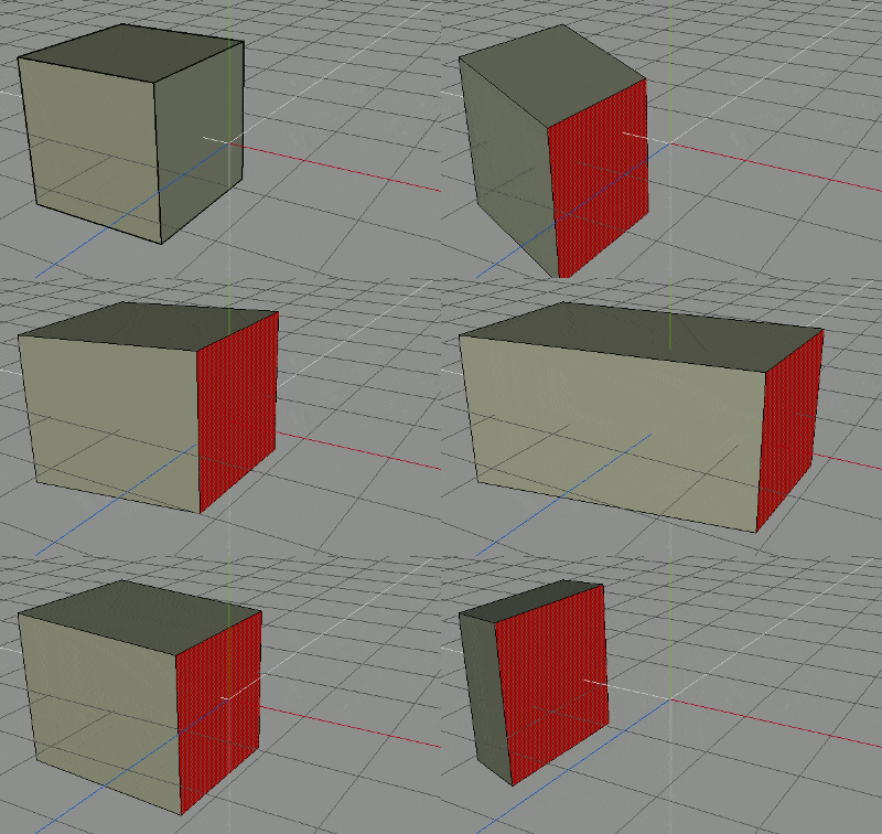
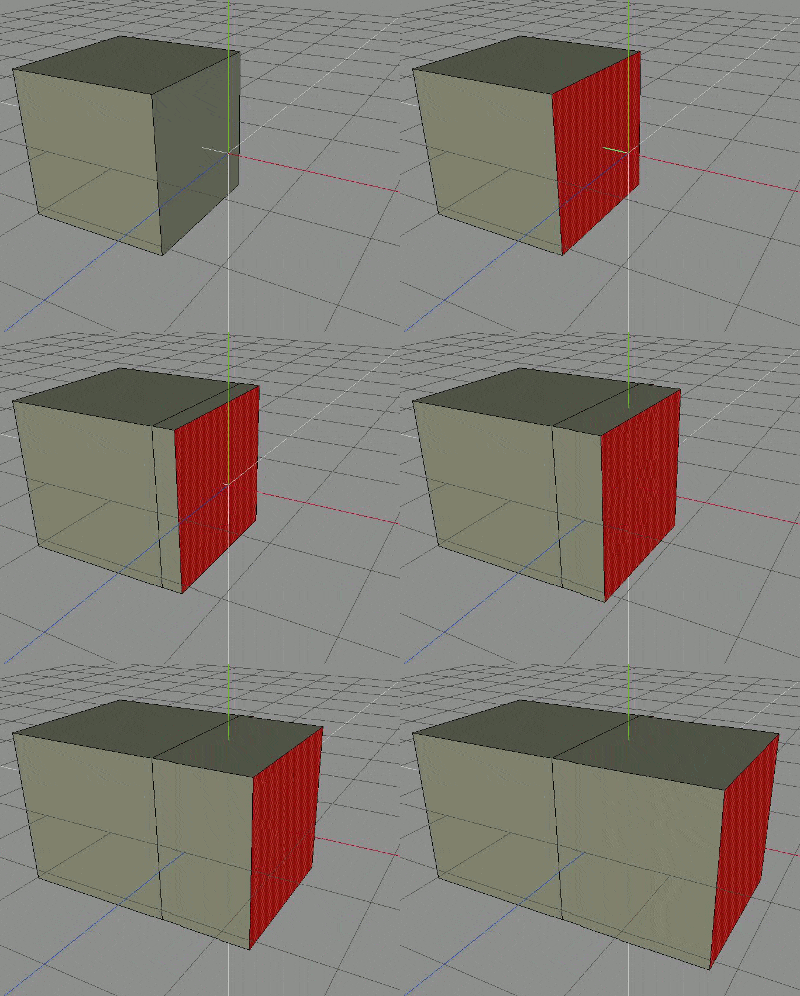
The image to the left illustrates translating ( or more simply moving ) a selected face in a couple of different directions. As you can see, moving a face can significantly change the size of the object. You can move along all three axis ( directions ) or you can constrain movement to only occur in a single direction, or even to “snap” movements to the grid or other objects.
Scale
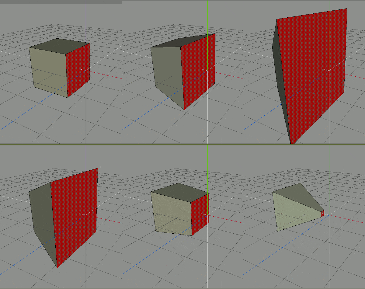
This image illustrates scaling a single selected face. Simply put, scaling makes an object bigger or smaller.
You can scale uniformly ( like the example ) which means the item will scale equally in all directions. You can also scale along a specific axis which basically results in squashing or stretching.
Scaling varies based on what the item is selected. Scaling a single vertex will do nothing while scaling two vertices will move them further apart or closer together depending on the direction you scale in. Additionally, scaling an edge will cause it to get longer or shorter.
Rotate
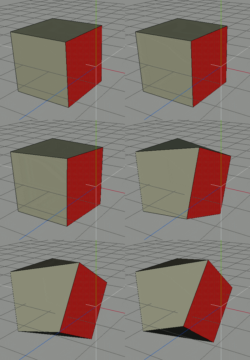
This image shows rotating a single selected face around a single axis.
You can rotate around any ( and all ) of the 3 axis. Rotation stays pretty consistent regardless of if you are rotating an object, a face, edge, or vertices. However, rotating a single vertex will have no effect.
All the previous commands are special in that they do not alter the underlying geometry. After scaling, translating or rotating, you still have the exact same number of vertices, faces and edges as you started with. The following operations however will change the underlying geometry.
Cut/Split/Knife/Slice/Connect
In box modeling, this is easily the most common command you will use and as you can see, it has a number of different names depending on the implementation. In the end they all basically result in the same thing, creating a new edge ( and thus two vertices ) across one or more faces.
If you are working at the face level, it’s called splitting, in that you are “splitting” the face one or more times.
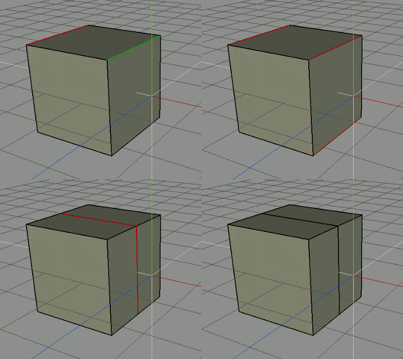
If you are working with edges, it is either cutting or connecting depending on the package you are using. The example image here shows cut/connecting 3 different edges. As you can see, once cut/connected, there are now twice as many faces as before. You can also cut/connect between vertices as long as they are part of the same face.
Some programs also support a knife tool, which allows you arbitrarily cut anywhere on a face or across a number of faces. You will also see various derivative cut operations, such as plane cut which cuts all faces along a certain plane.
In the end they all serve the same purpose, to add details to your mesh. With just cutting and the three previous translations you can start with just a box and create any shape imaginable!
Extrude
The image to the left illustrates extruding ( or pulling ) a selected face along a single access.
Essentially when extruding you can select a face and “pull” it out, which causes completely new geometry to be formed. Extruding is a good way to add geometry to your mesh. You can extrude along any axis or simply along the normal ( the direction the face is um… facing ). You can also extrude many faces at once.
If you are thinking to yourself extrusion could be achieved by scaling your object then cutting/splitting all the way around the middle, you are exactly right. As I said earlier, you can accomplish just about anything using just the cut tool. But extruding sure makes the task a hell of a lot easier! Next to the cut tool, extruding will probably be your most common modeling task.
You can also extrude edges and sometimes vertices but the behavior varies massively between applications. Generally though extrusion is done on faces.
Bevel
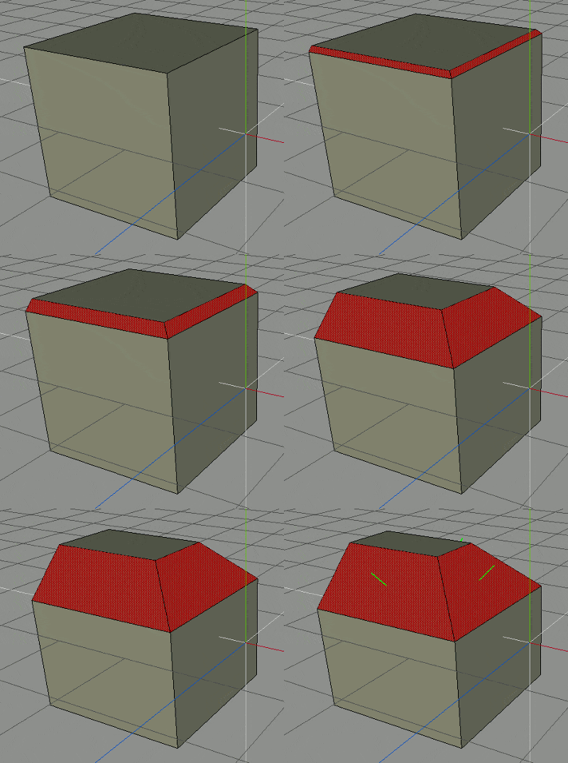
This top most image shows beveling 3 of the top edges of this cube.
Basically beveling is for creating or adding details to a corner. Essentially it adds additional geometry at an angle offset to the item you have selected. Yes, once again you could accomplish the same thing using a series of cuts and transforms.
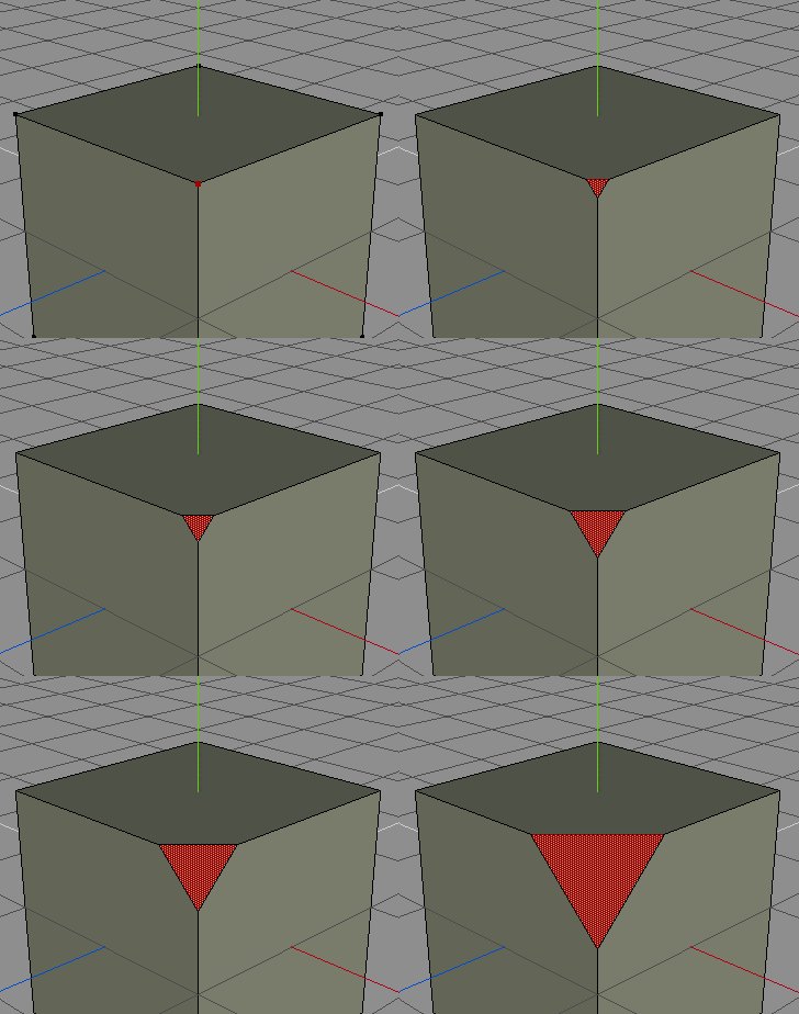
The bottom most image illustrates what happens when you bevel a single vertex ( in Wings ). As you can see, additional geometry is created at an offset angle to the selected vertices, but the behavior is vastly different from beveling an edge. The same use applies though, rounding off an otherwise sharp corner by adding more geometry around the selected item.
Bridge
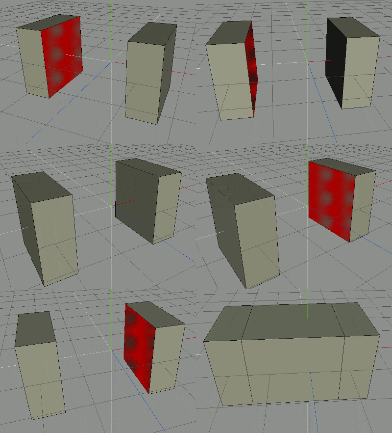
This image illustrates “bridging” off two faces.
Essentially you select two faces from two separate objects then the application creates the geometry between them to turn them into a single solid object ( and then removes the two selected faces ). This is a common way to connect together two meshes that were modeled separately.
There are a few caveats though and it depends on the program you are using. Often before you can bridge two faces together, the two separate meshes need to be combined/connected into a single object. Again, how this works varies from application to application, in Wings you select both objects and click “combine”. Some programs also require the two connecting faces to have the same number of edges. ( Wings does not, it will automatically make more edges as needed in the ‘bridge’ ).
Weld
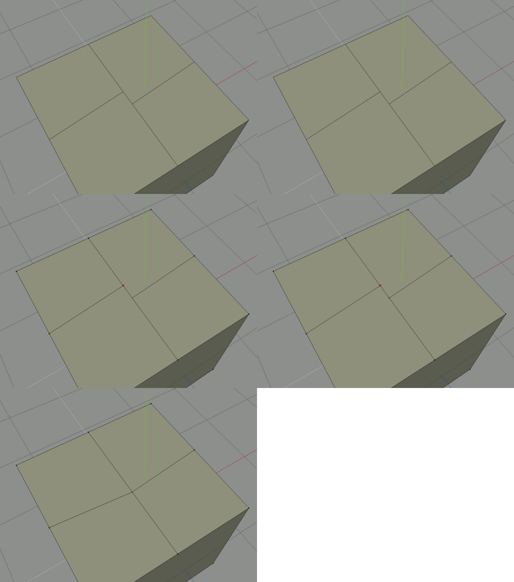
The image to the left illustrates welding two vertices together. Welding “welds” or merges a number of different vertices together into a single vertex.
Welding only works on vertices and is an effective way to clean up your mesh and reduce the amount of geography that needs to be rendered. Once two or more vertices are welded together, it gets rid of any left over edges and obviously reduces the number of vertices to one.
Welding works differently from application to application. In Wings you select a vertex, click weld then click the vertex you wish to weld together. In 3D Studios, you move the two vertices close together, select both then choose weld. The end result is the same.
There are obviously dozens or even hundreds more operations you can perform while modeling, but this small handful are the ones that you will use the most. Using just these operations you can make remarkably detailed models.
If you are interested, you can watch all of these operations (and more) in action and learn how you perform them in my Introduction to Wings 3D video. Obviously if you are using a different modeling application the details are going to be different, but still very similar.

