Now we are going to continue adding details. Frankly the only reason for Part 2 and Part 3 being separate is space, the process continues and remains nearly identical. This is also the part that requires the most artistic ability, having an eye for where to add detail and where not to. In the end, we will mostly be using the same basic tools, extrudes and edge loops.
Adding the Air Intake
Let’s start off by adding the air intake. We want to start here because we have a single face to work with, which wont be true in a few minutes. Ideally you want to sketch in the major details before you start adding a bunch of geometry.
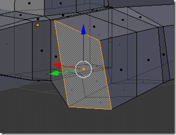
Select the polygon at the front and to the over from the cockpit.
This guy:
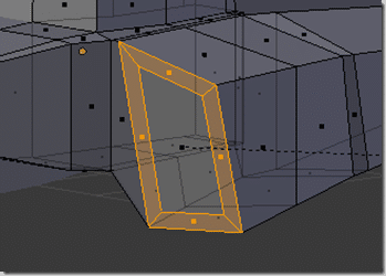
Press I to inset the face, then move the mouse until its set in about 15%, left click when done, like so:
EDIT: Oops, I totally forgot to extrude the intake at this stage… see “Fixing my Oops” later on to see the step. You could have done it before adding the wing and it would be marginally easier. In the end, the results are exactly the same. If you are wondering… why didn’t he? It was mostly because I forgot to do it at the time, and it would change all of the geometry in the screen shots so I’ve just gone with an edit instead.
Adding the Wings
Now we want to add the front and rear wings ( well, rear stabilizer to be more correct ) to the plane. This is accomplished with a series of loop cuts.
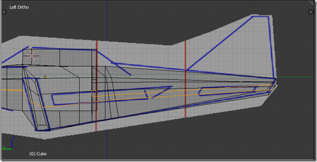
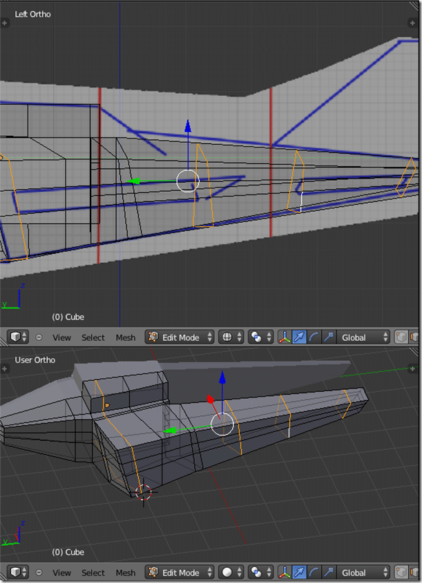
We want to apply two cuts down the side for the top and bottom of our wings. Here they are in the side view in X-Ray (Z) mode.
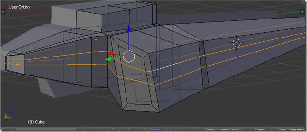
Or slightly easier to see selected at an angle:
Now add a vertical edge loop at the front and back of both the forward and rear wings, like so:
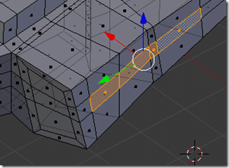
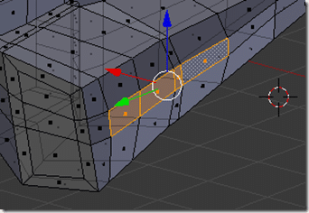
Now before we create our wing, we want to flatten/straighten the polygons that make up our wing. This part may seem a bit unintuitive, but it is handy. First you need to select the faces you want to align:
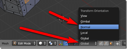
Now switch from Global to Normal mode. This makes the X,Y,Z values become relative to the selected face, not global values.
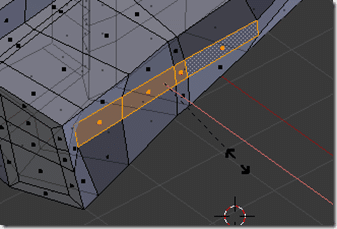
Now we want to Scale to 0 along the X axis. ( Press S then Z then 0 ) then left click to apply. It should before perfectly flat, but a bit off.
NOW SWITCH BACK TO Global! And rotate about the Z axis ( R then Z ) until its back in line with the rest of the mesh. Then Translate along the X ( G then X then move mouse ) axis until the faces are budging slightly out from the side, like so:
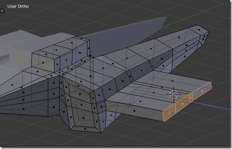
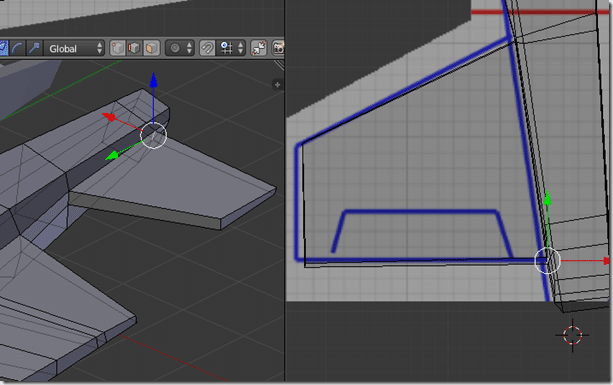
With the faces still selected, press extrude and pull the wing out to roughly match the reference image:
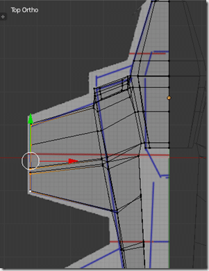
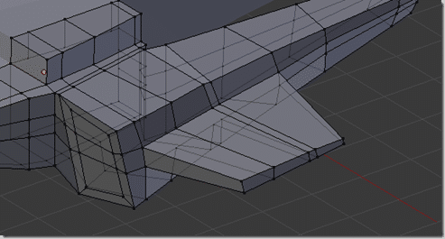
Now using a combination of transforms, scales and rotations, move the wing to match the reference image. I also thinned the wing slightly by bringing the bottom edges of the wing up toward the top edges. In the end it should look like:
Now we repeat the same process for the rear wing. Fortunately it’s a single polygon right now, so we don’t need to flatten it, simply extrude it and move to match the reference image.
Fixing my oops…
At this point I noticed I forgot a step back when I created the intake. Keep in mind, this would better be done at the stage when the air intake was a single face ( before we did a number of loop cuts ). We can however fix it now. The end result is identical.
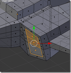
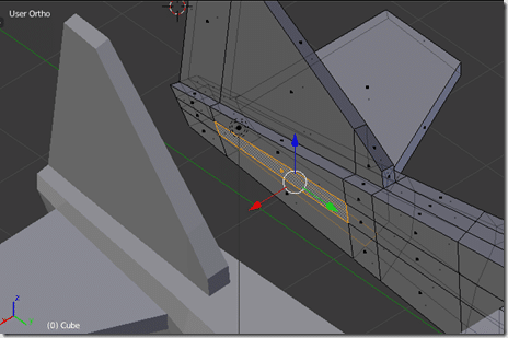
Grab the face/faces that make up the inside of the air intake we modelled earlier:
The only real difference is, now there are three faces, while if you performed this before the edge loops where added for the wings, there would have been only one face to work with.
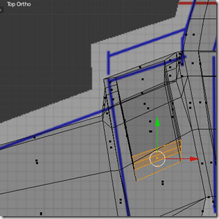
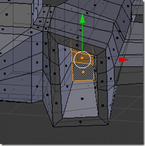
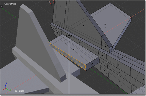
Extrude these faces ( E ) and pull it back within the mesh.
Move and scale as required to keep it somewhat centered within the rest of the tail geometry. In the end, the intake should look like:
Ok… mistake corrected, now lets create the tail section.
Creating the tail.
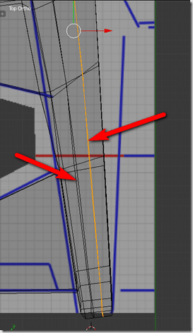
First create a pair of loop cuts along the tail, like so:
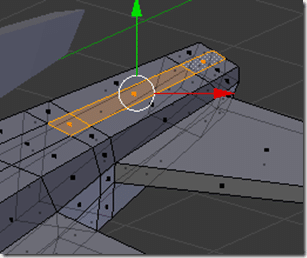
Now selected the following faces:
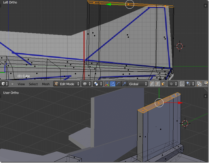
And in the side view, extrude along the Z axis, like so:
Now in edge mode, move the top most edges to look like this:
Creating the tail wing
Finally, lets create the tail wing.
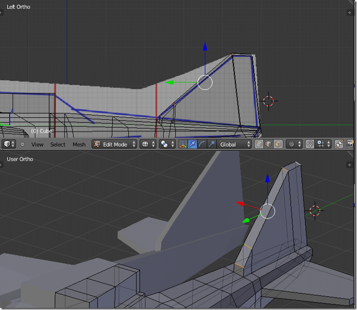
First select this face:
Extrude it inward along the X axis ( E then X ) like so:
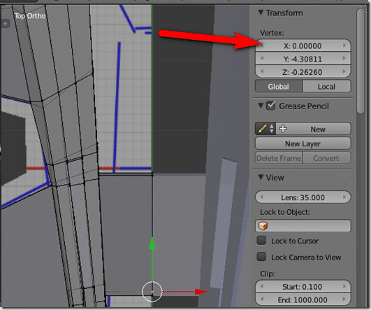
Since we are modelling about the origin, I switch to Vertex mode and select each vertex of the face, and in the Properties(N) window, set the X value to 0. As you can see, the wing joins up perfectly with the mirrored image:
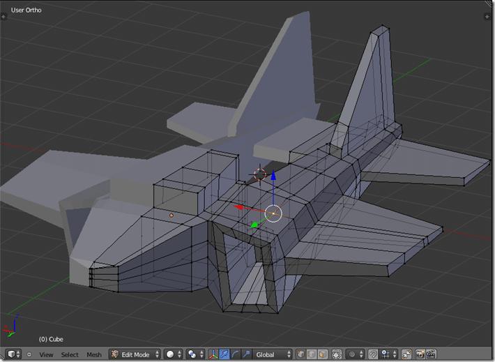
At this point our jet is starting to look much more jet like
Most of the shape is there now, just need to shape the cockpit and engine, then its mostly a matter of cleaning up.
Click here for the Next Part

