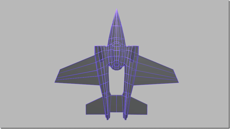
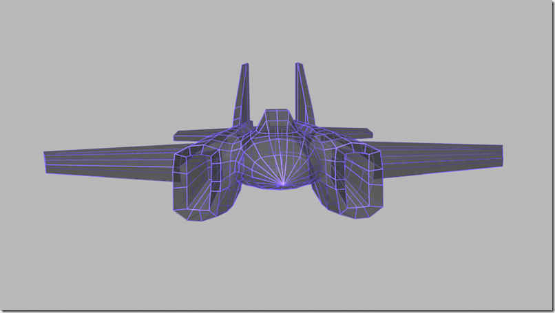
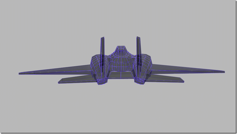
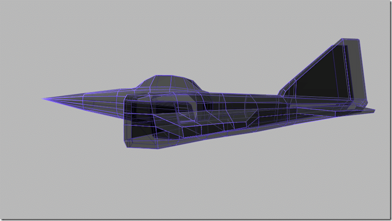
In this post we are going to, for the most part, complete with the modelling portion. In the end, I am going to stick with a relatively low polygon model so it can easily be used in a real-time 3D game, as well as for rendering a sprite. Additionally, a lower polygon count makes texturing more straight forward. That said, if you are rendering to sprites, the polygon count really doesn’t matter to you ( except of course for your PC being able to run Blender that is! ). Later on I may take a look at adding more detail, as well as rendering a normal map to give the illusion of more detail on a low polygon model. That said, I cant spend forever on this or we will never get to texturing!
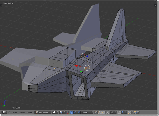
So… back to our model. In our last stage we ended here:
Certainly more jet like than box like, but there are obviously some major exceptions. First the cockpit is still basically just a box. Second, the nose is about as aerodynamic as a toaster at this point. Third, there is no engine yet, although you could argue that is just wasted polygons given the shape of the jet ( aka, you cant generally see the engine… ), so for now I am simply going to skip modelling an engine. Finally we can do a bit of tweaking and movement in general.
The Cockpit
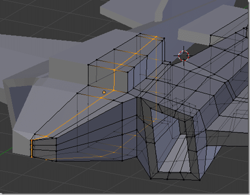
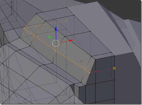
First we start off with our friend the loop cut. Create one more loop cut along the edge of the cockpit like so:
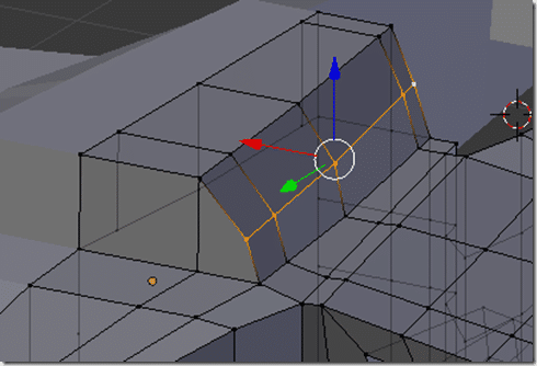
Now move the outer edge of the cockpit down a bit, like so:
Now we are going to create out first triangle! A few triangles here and there aren’t a bit deal, especially if they make sense. What we want to do is basically change our edge loop so it loops around the cockpit.
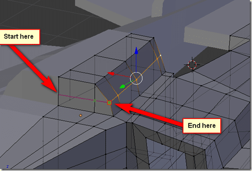
To do this, we are going to make use of the Knife tool. You use the knife tool by hitting K, then clicking here you want to start cutting from, then click where you want to cut to. Finally click enter to complete the cut. Hit K then click on the two locations marked. Be sure you get the special square indicator that shows you are cutting to an existing vertices or you will create extra un-needed and un-wanted geometry.
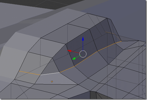
Now repeat the process for the back of the cockpit and your new edge loop should look like:
Now shape the cockpit to suit. I am not all that pleased with the initial results, so I will probably tweak later, but its at least a cockpit now instead of a box.
Modelling the nose
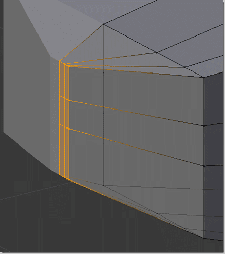
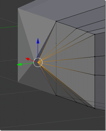
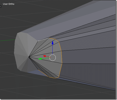
Now let’s do something about that nose. We are going to collapse all of the vertices at the end into a single vertex.
Box select all of the vertices at the front of the jet, like so:
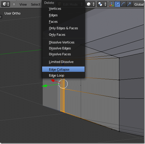
Then hit X and choose Edge Collapse
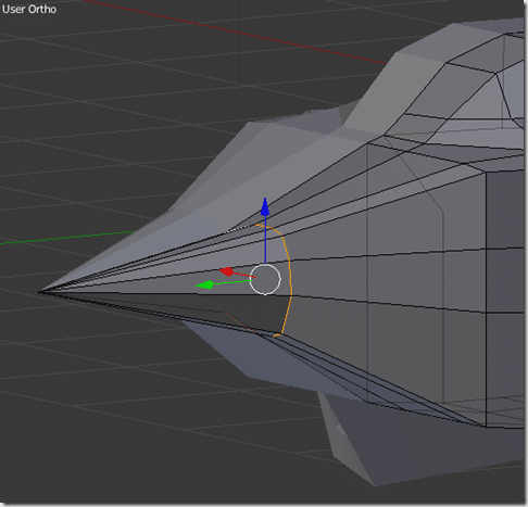
And Voila!
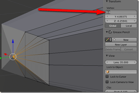
As you can see above though, our newly created uber vertex isn’t at the mirror point any more. Make sure to move it back to 0 along the X axis:
Now we have one small problem… our plane is really really really boxy and we don’t want that! You can spread the vertices out by hand but there is a much easier solution.
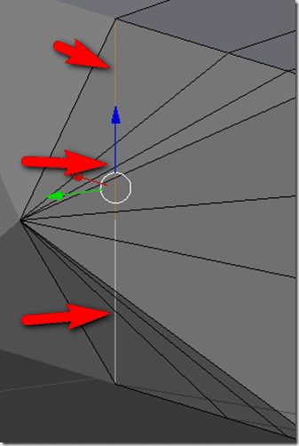
First make sure you don’t have any interior geometry ( lines/vertices created along the X axis ) , like I do now. You will need to be in Xray (Z key) mode to spot extra geometry.
If you do, select the edges and delete them ( X ).
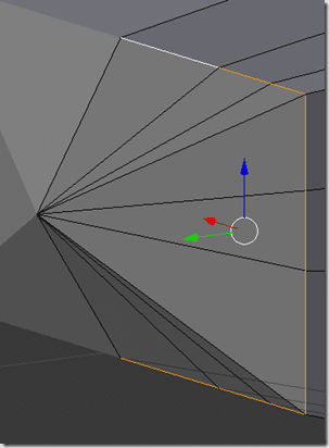
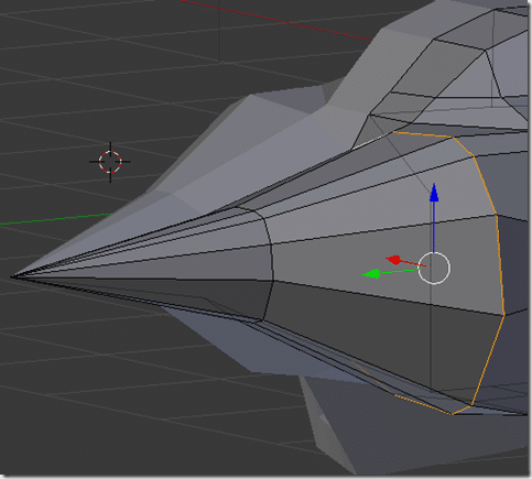
Now select the boxy edge loop making up the front of our nose:
And run the To Sphere tool. ( Alt + Shift + S ) and:
Now move the selected edge loop back from the front of the nose:
Now repeat the same process with the next edge loop ( closer to the cockpit ).
Obviously we have a bit of cleaning up and tweaking to do now. After a couple tweaks and moves we have:
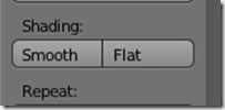
At this point I turned off the background reference images and played around by hand and selectively set smoothing. To set smoothing, simply select the face you want to be displayed smooth and click Smooth under Shading in the tools panel:
I made a number of small tweaks, such as extending the wings, shrinking the cockpit and main body and just smoothing things out.
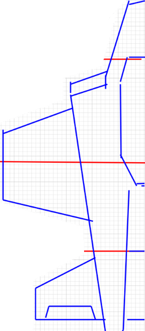
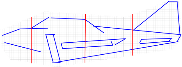
So, this was our original design:
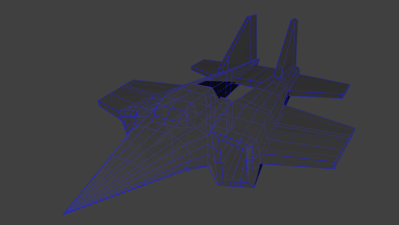
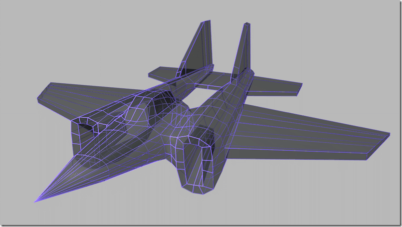
And this is where we ended up:
Pretty close to my original concept. Not perfect by any means, but I’m happy.
You can download a zip containing the blend file right here.
Time to move on to texturing!
Click here for the Next Part

