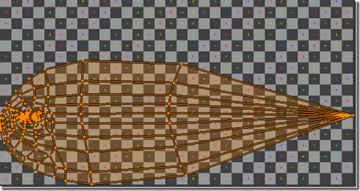
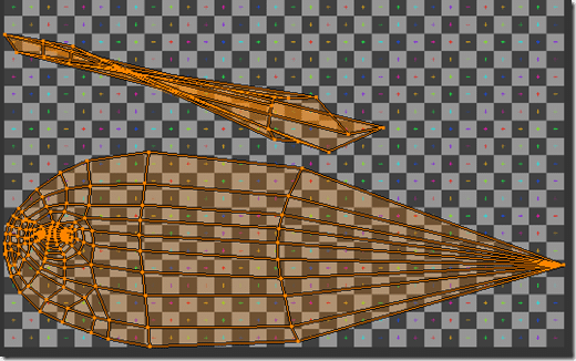
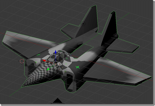
As I mentioned in the prior tutorial section creating a UVMap is basically like wielding a pair of virtual scissors to cut your 3D object up so it can be smushed flat. As we saw earlier, the default unwrap map is pretty, subpar:
Default unwrap:
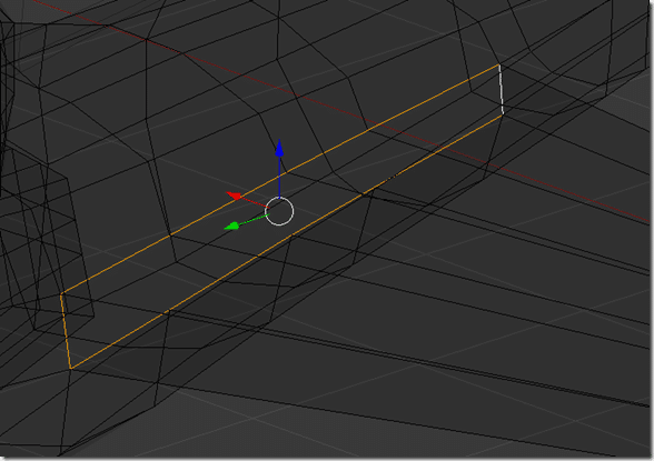
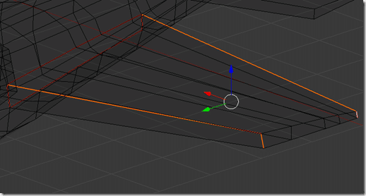
Let’s start cutting things up. First we will default the wings. In 3D view, make sure you are in Edit mode and Edge selection, then select the edges at the base of the wing, like so:
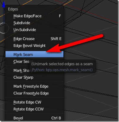
Now we want to mark the selected as a seam. Press CTRL + E to bring up the Edge menu, and select Mark Seam.
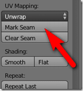
Or you could use the button in the Tools panel of 3D View:
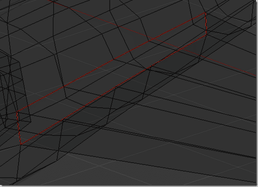
Both options do exactly the same thing. Once the seem is marked it will appear as red:
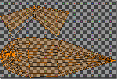
Now you can see the result of marking a seam. In 3D view, select all edges ( A ) and take a look at the UV window:
We now have a completely separate collection of UVs ( called a UV island ). I still wouldn’t want to paint over these UVs yet, so we have a bit more work to do. In order to be able to flatten the wing even more, lets mark another set of seams, like below:
Now look what happened to the UVs
That is certainly much easier to paint over! Of course, you could have split the wing top and bottom easy enough but each additional seam makes painting a bit trickier.
Remember the textured view of our jet from the previous tutorial:
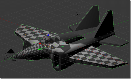
Instead of a checkerboard texture on the wing, you just got a white blotch. Now that we marked the wing seams, look at the result:
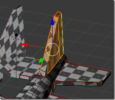
MUCH better! Ultimately our goal is to make the entire jet have a checkered texture like that. The process is exactly the same, just keep marking seems in the model until the UV layout makes sense. Let’s repeat the same process on the back wing and then the tail. If you make a mistake, you can simply Clear Seam on the selected seam. To completely undo your changes, select all edges and do CTRL+E –> Clear Seam and you are back to default.
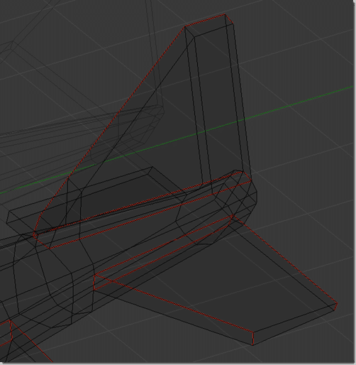
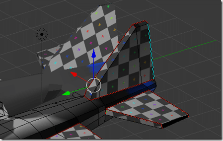
I marked the following seams on the back tail and wing:
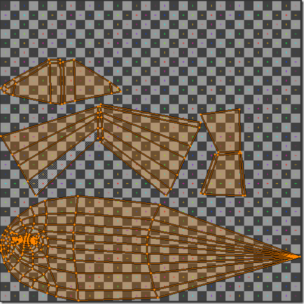
Resulting in this UV layout:
And in our rendered view:
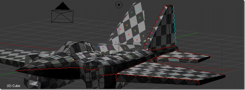
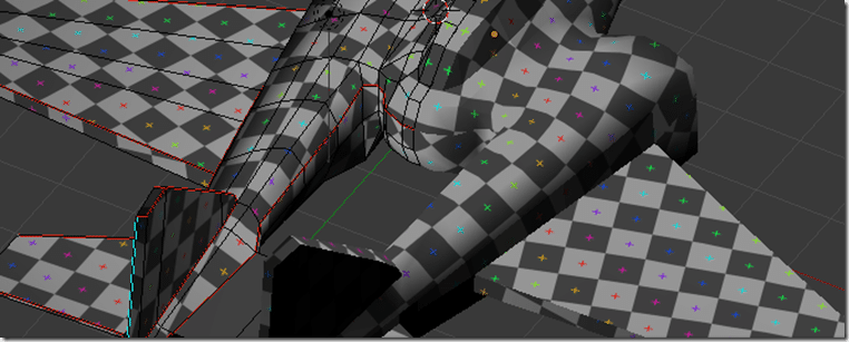
Next lets cut the jet in half vertically. Select the continuous loop all the way around the jet, it will meet up with the wing cut:
Front:
Back:
Highlighted:
You want a continous edge around the entire jet that will cut it between top and bottom. Once selected, mark the seam.
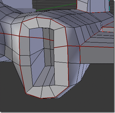
Now mark the area surrounding the air intake:
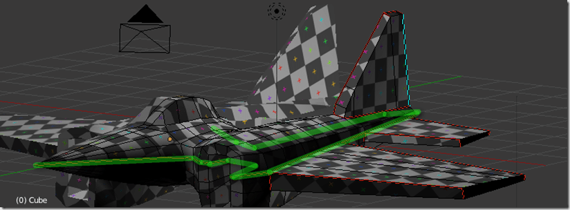
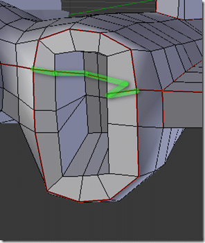
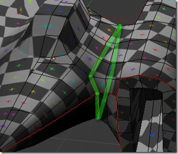
This however results in an unwanted seam, shown below marked in green:
Select those edges and then select Clear Seam.
Now we have:
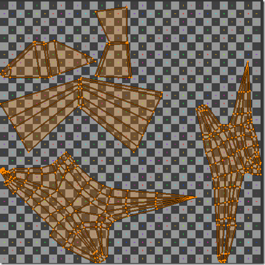
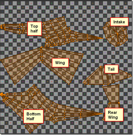
And the following UV layout:
Keep in mind, Blender automatically sets the positions, so yours might be a bit different layout wise.
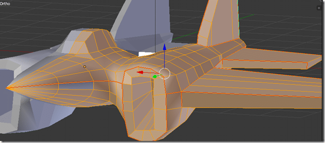
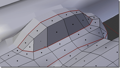
Finally, lets seperate the cockpit away from the fusalage:
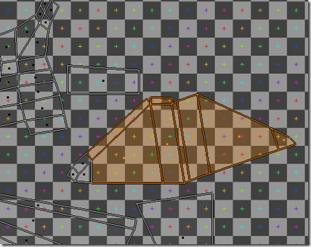
The cockpit:
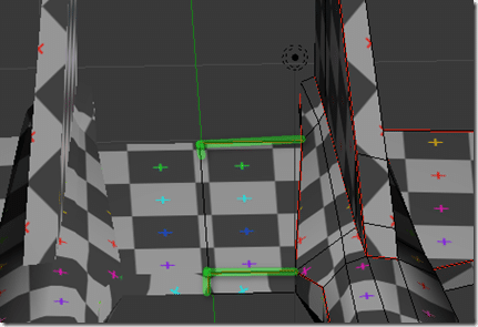
And finally, the tail:
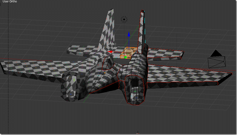
And now our fully UV mapped model:
As you can see, the texture pattern flows pretty well over our image. There are portions where we might get into a bit of trouble but they aren’t areas where we are going to need details, so we should be good to go!
Well, that sucked, there has to be an easier way!
Yeah, actually, there is. Blender has something called a Smart UV Project. To use it, in 3D View, in edit mode, select all, then press U. In the resulting menu select Smart UV Project:
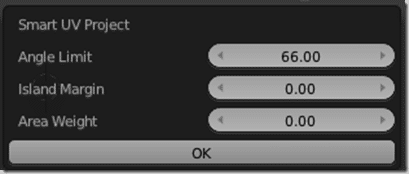
Then a dialog will appear:
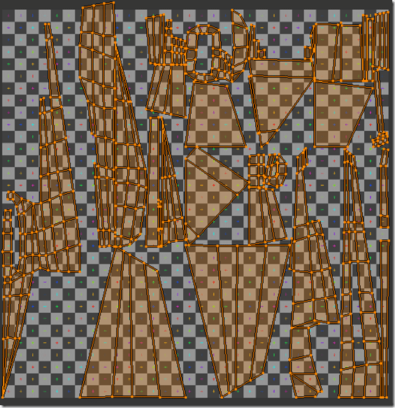
As I understand it, Smart UV looks at your model and separates UVs based on the angle between shapes. So for example, since the wing essentially meets the fusalage at 90 degrees, it will easily be split into it’s own UV group. Play around with the angle limit until you get a grouping you like. Here is the result at 66 degrees.
Not ideal, but certainly a hell of a lot easier!
We only touched on a very small bit of what you can do with UVmaps. Just keep in mind, if you add another seam ( and thus generate another Unwrap ), the positions will be reset. Otherwise you can scale, turn, relocated, etc… UV coordinates to your hearts content. If you don’t want them to be scaled again, you can Pin (p) a UV in place.
Selection Options
You may find that you want to select Polygons from the UV layout screen. By default it’s setup that what you select in the 3D view will be selected in the UV view, but it’s possible to do the opposite.
You need to click the “Keep UV and edit mode mesh selection in sync” button.
Now making a selection ( such as using the B)ox select mode ) in the UV window:
Will select the corresponding polygons in the 3D view:
Click here for the Next Part

