In this section we will look at the various operations you perform when modelling in 3D. Much like when working with clay in the real world, you can actually make some remarkably detailed work with only a small number of tools.
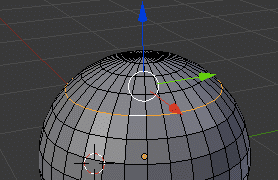
There is one concept we haven’t really touched on as of yet, and that is the edge loop. An edge loop is important concept in modelling, as the edge loop is ultimately the contour or backbone of your model. You can select, move, remove and add edge loops all at once, allow you to make huge changes to a model quickly and easily. When modelling in Blender, it is important to keep edge loops in mind. For a better description of what an edge loop actually is be sure to check this post out.
Edge loops in Blender
There are a number of operations you can perform on edge loops.
First and most obvious is selecting an edge loop:
Selecting an Edge loop:
To select an edge loop, first switch in to Edit mode ( Tab ), then set Mesh Select Mode to edges ( CTRL + Tab + 2 ).
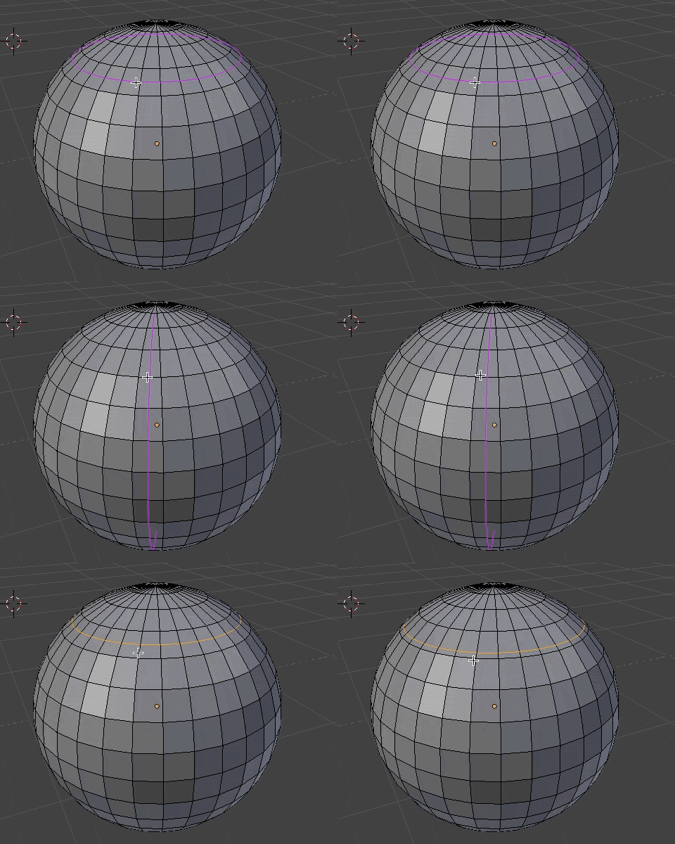
Hold Alt + Right click and edge and the entire edge loop will be selected. Holding down SHIFT allows you to select multiple edge loops.
Deleting an Edge loop:
Select an edge loop.
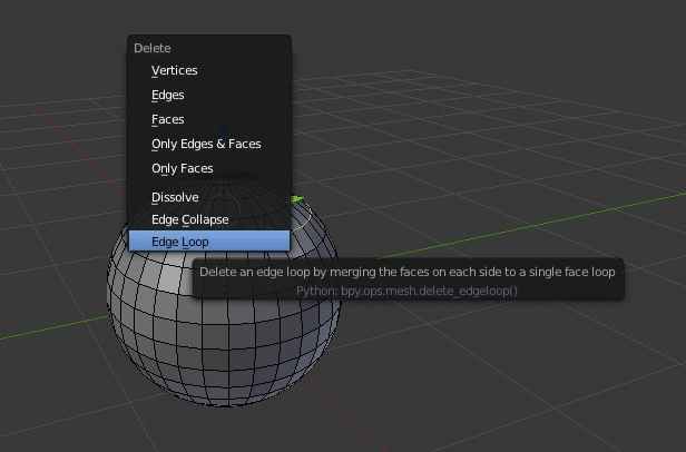
Hit X. In menu select Delete -> Edge Loop
Loop Cut and Slide
Loop Cut and Slide is a great example of how edge loops allow you to quickly add detail to a mesh be inserting an additional edge loop. It is essentially two operations in one. First you create a new edge loop parallel to an existing one, then you “slide” it, which is equivalent to moving while maintaining the shape of the mesh.
First switch in to Edit mode ( Tab ), then set Mesh Select Mode to edges ( CTRL + Tab + 2 ) if not already in edit mode.
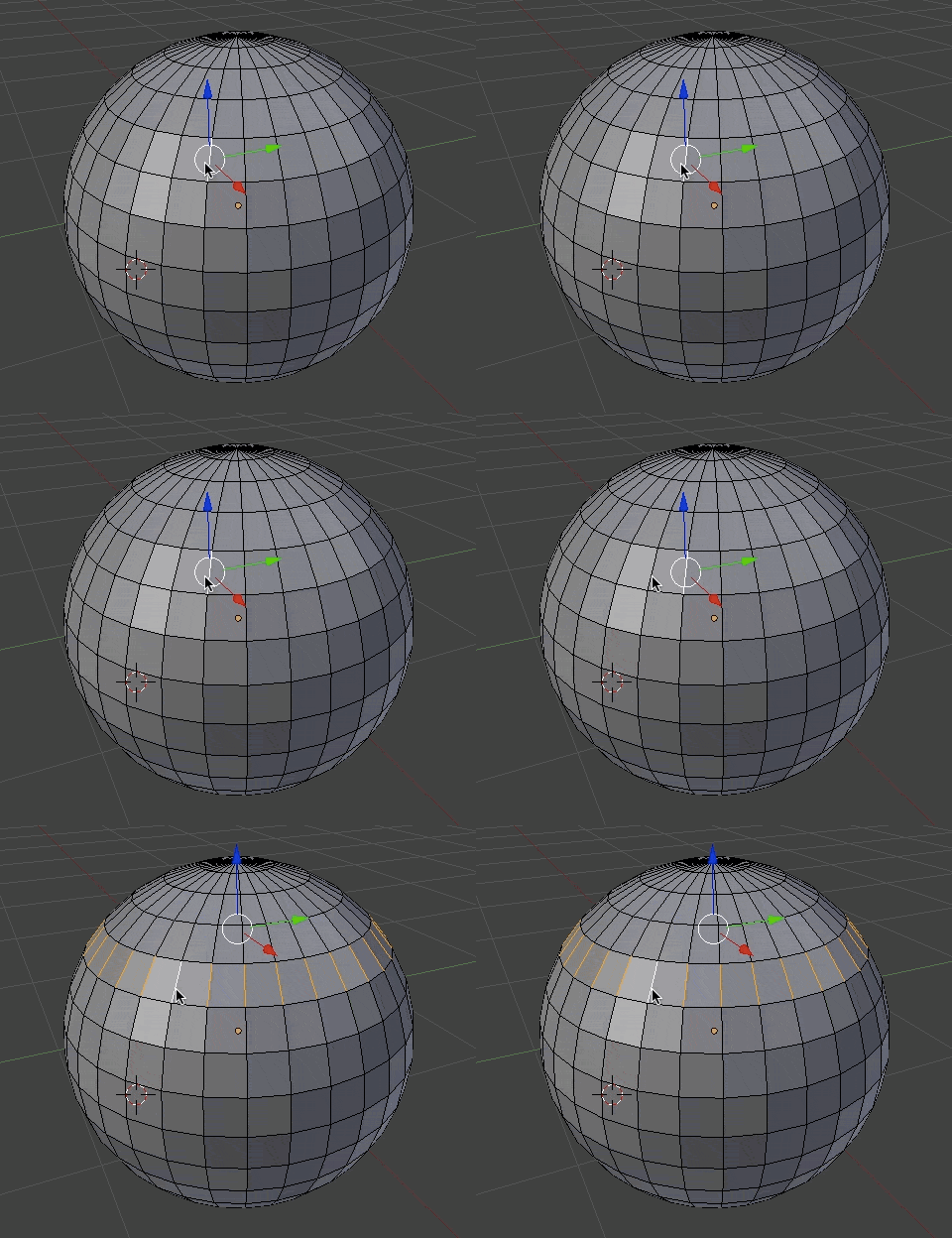
Hit Control + R
Move the mouse to select which direction you wish to create the edge loop along, an indicator will be displayed on screen.
Left click to select the direction. Indicator will change colour.
Move mouse up and down, or left and right, depending on the direction of the edge loop to move the loop along the surface, Left Click to commit. Right click to cancel.
In addition to using CTRL + R you can perform a loop cut and slide using the following button from the tools menu:

Edge Rings in Blender
An Edge Ring is very similar to an edge loop, but it selects the perpendicular edges instead.
Selecting an Edge Ring
First switch in to Edit mode ( Tab ), then set Mesh Select Mode to edges ( CTRL + Tab + 2 ) if not already in edit mode.
HIt Control + Alt + RIght Click on an edge in the edge ring.
Common Modelling Operations
Now we will take a look at some of the most common operations performed while modelling in Blender.
Extrusion
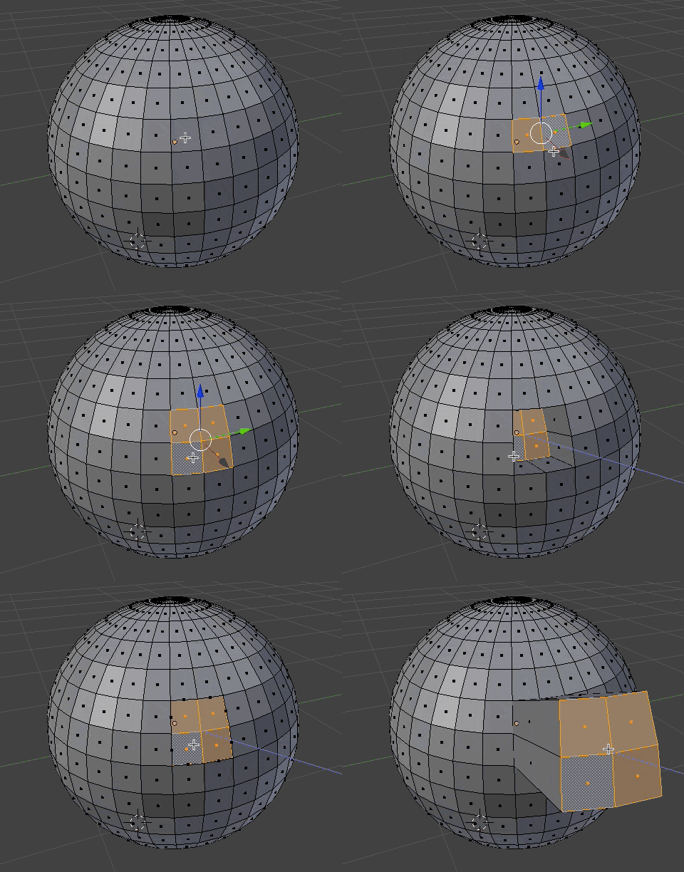
Extrusion is a very common way to add more detail to a model. If you were modelling in clay, think of extrusion as the act of pulling out or pushing in a portion of the clay. You can perform an extrusion on multiple selected items at the same time and it can be performed on vertices, edges and faces, although faces are the most commonly extruded type. It’s important to know, if you perform and extrusion with no movement, new geometry is still created, it’s just directly over top of existing geometry! If you cancel an extrusion, make sure you have properly undone it, or you can create unwanted polygons.
First switch in to Edit mode ( Tab ), then set Mesh Select Mode to faces ( CTRL + Tab + 3 ) if not already in edit mode.
Right click select the faces you wish to extrude.
HIt ‘E‘ and then move the Mouse left to extrude “in” or right to extrude “out”. Left click when complete.
You can optionally hit ‘X‘, ‘Y‘ or ‘Z‘ to constrain the extrusion to a certain axis.
Knife Tool
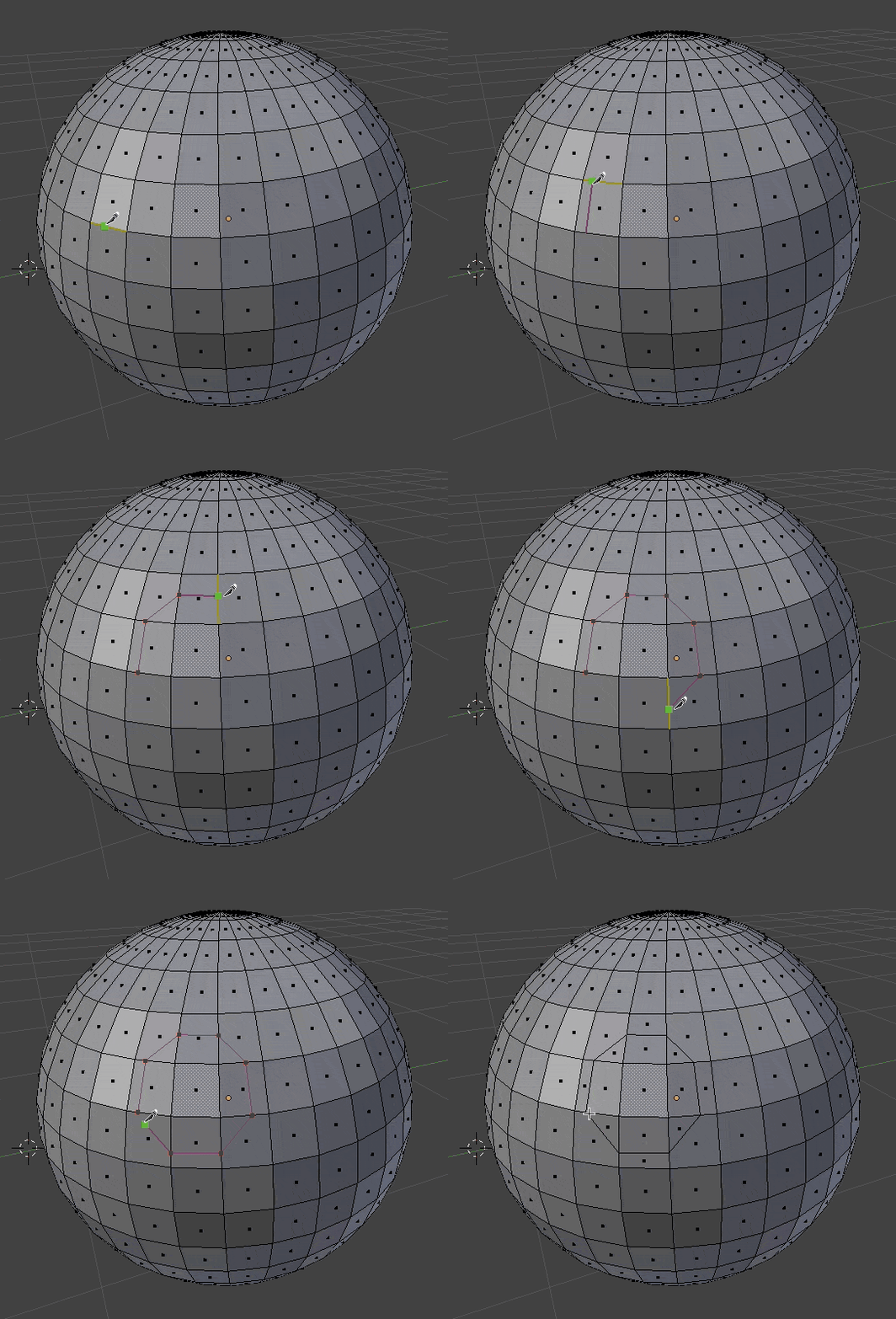
Using the knife tool allows you to add new edges to existing geometry easily. The knife tool automatically creates new edges where you cut.
In edit mode, press K.
A green dot will appear where the cut will appear.
Left click to make cut, move mouse and repeat.
Press Enter to complete cut.
Holding Control while performing a cut automatically centres the cut location between the two bordering vertices.
Create Face
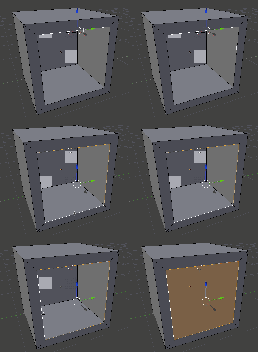
You can easily create new geometry using the create new face tool.
In edge mode ( Ctrl + 2 ), holding down Shift and left click to select the edges surrounding the face you wish to create.
Once complete, press ‘F‘ and a face will be completed.
This process will also work when working with vertices and allows you to create faces with more than 4 edges.
Inset
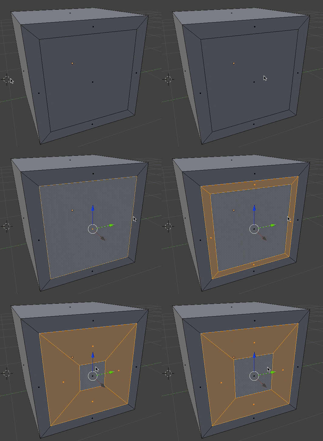
Inset works a lot like extrude, but instead of pulling the geometry out of the mesh, it insets a face within an existing face. Its a good way for adding detail within a polygon.
In edit mode, select one or more faces to inset.
Hit ‘I‘ to inset face. The distance you move the mouse toward the centre of the face determines how much it will be inset. Left click to finish.
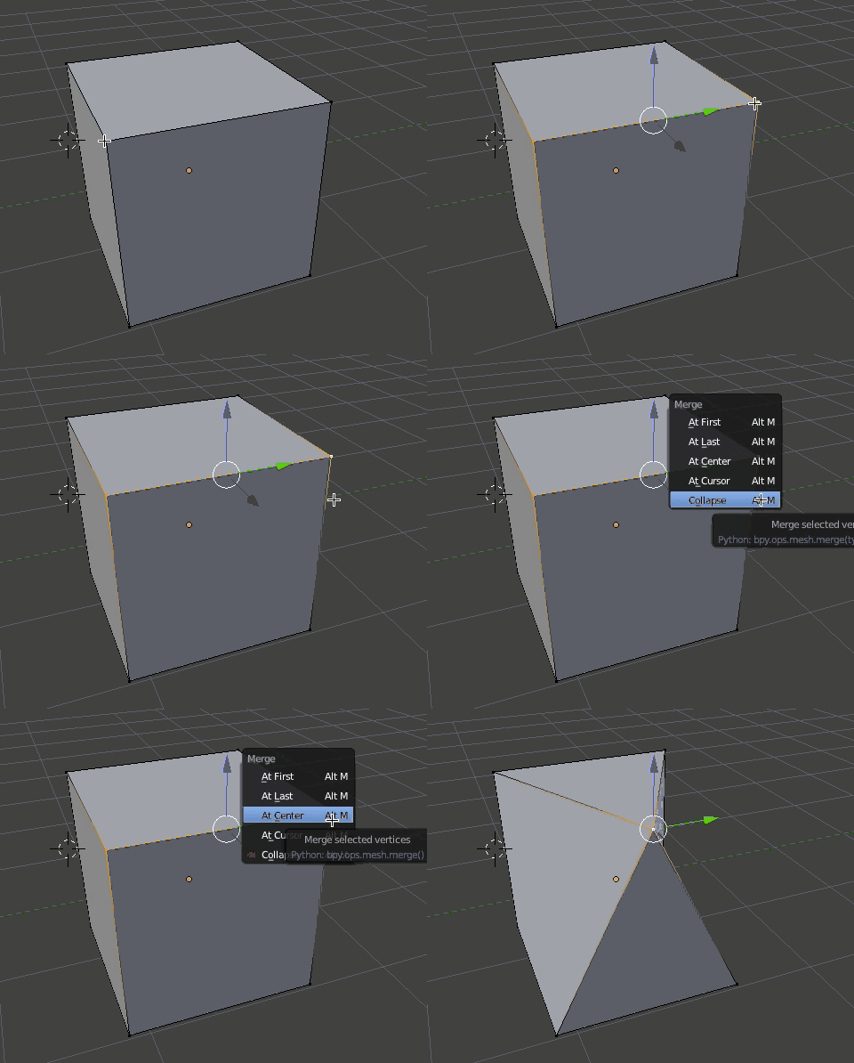
Merge/Collapse
Sometimes you have too much or unwieldy geometry and you want to get rid of some of it. This is when the merge tool comes in handy.
In edit mode, select two or more items you wish to merge.
Hit Alt + M
In the resulting menu, select how you would like the merge to perform.
Change Subdivision Level
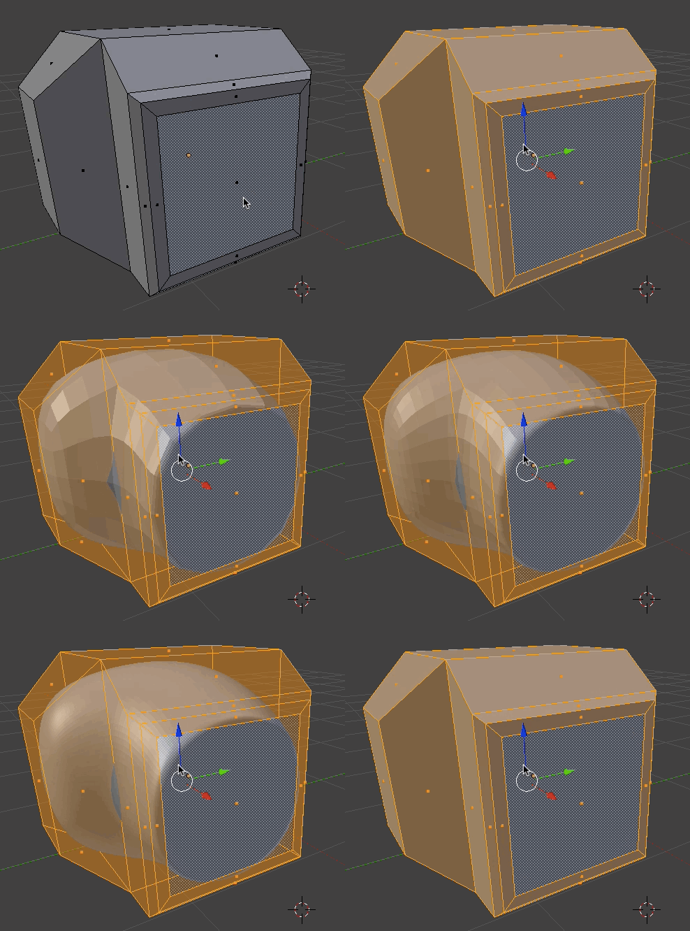
A very common modelling technique is called subdivision surfaces. Essentially you model a rough outline of the shape you want to create, then add detail to it by sub-dividing it over and over into more detailed geometry.
Select the geometry you want to subdivide.
Press Control + 1/2/3/4 or 5. Press Control + 0 to reset to no subdivisions. Do NOT use the number pad numbers.
As you may notice, the original hull is preserved while sub-dividing. You can still work on the source shape and it will be updated in the subdivided mesh.
You can also permenantly sub-divide geometry by pressing W then typing subdivide.
Hotkeys / Actions used in the Tutorial
| Key/Action | Action |
|---|---|
| ALT + RMB | Select edge loop |
|
X Select “Delete edge loop” |
Delete edge loop |
|
CTRL + R |
Loop cut and slide |
| CTRL + ALT + LMB | Select edge ring |
|
E |
Extrude |
|
E + x, y or z |
Extrude along axis |
|
K |
Knife tool |
| F | Create Face |
| I | Inset face |
| Alt+M | Merge/Collapse |
| CTRL + 1,2,3,4 or 5 | Set sub-division level |
| CTRL + 0 | Turn off sub-division |
On to quick reference

